Hardware Design and Development Tools / Technologies
The first analysis is an opportunity for our intuition.
The first step in developing the hardware is analyzing the entire system.
As hardware design engineers, we use standard office software to draw the first level diagram and noise budget, sometimes as simple as MS Excel.
Of course, we can use some more sophisticated and expensive tools, but most projects do not need such an overkill, and the benefit is usually not very high.
Our long-term experience allows us to get the same performance from the standard cheap tool as from an expensive high-power tool.
The simulation of the hardware components shows us the physical limits.
We efficiently utilize the Spice family's tools for the linear and non-linear analysis at low frequencies. Although they are very often free of charge, in most cases, they are sufficient.
Another step we take is the simulation of each hardware component.
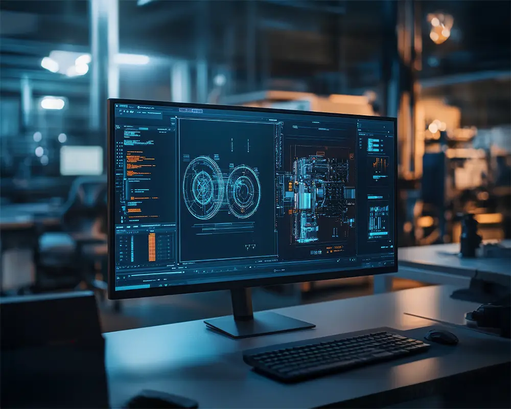
Physical accuracy comes from understanding the model, not from the cost of the simulator.
The mechanical model enables us to design an excellent manufacturable product.
As a vital part, our mechanical engineer creates a 3D model for the product from the mechanical point of view. The model is then modified and optimized to achieve the requirements defined in the main definition phase and to be compatible with the electronic design.
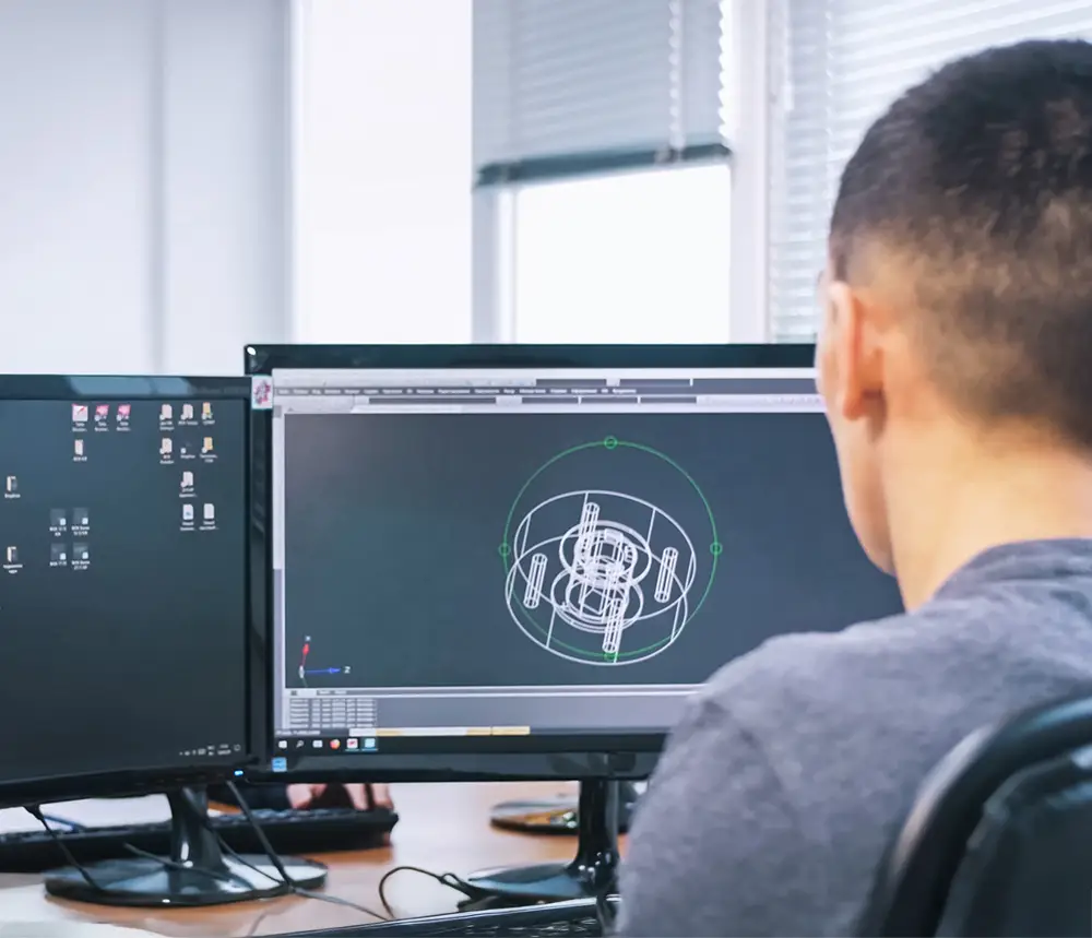
Good mechanical design works for the PCB and for production.
Radio Frequencies – our experience is an ace up our sleeve.
We use the most common brands of tools according to their purpose. Some tools allow full EM analysis, others are very powerful in non-linear simulations.
If they technically meet all the requirements, we also use tools that are free, which allows us to minimize the cost of simulation time and save some of the development budget.
We export the data for further development stages as soon as we optimize the PCB structure via these tools.
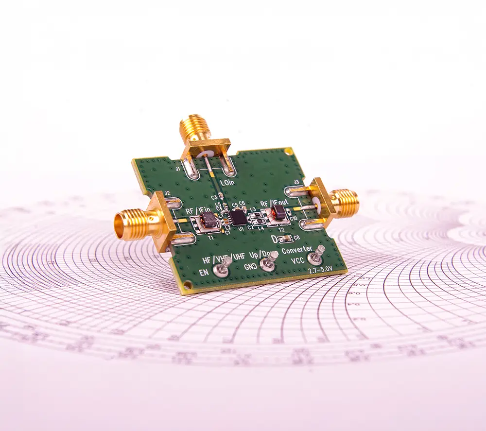
Combining the right RF tools delivers reliable results that single-tool approaches cannot match.
PCB design is the circuit visualized into real data.
Once we have all the necessary components simulated and optimized, we go to PCB design. We design the wiring diagram, interconnect all the components and forward the final model to the PCB design team.
They then convert the model into the form of concrete circuit boards. This process is carried out manually and the know-how of our expert team and their many years of experience in PCB design are significantly involved. The electronic parts must of course also be designed with the desired physical form of the product in mind.
As soon as they are finished with the PCB layout, they export PCB production and assembly data for review.
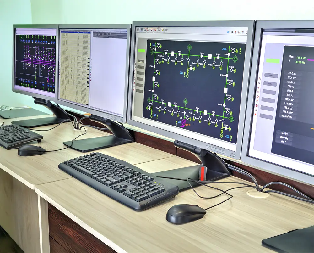
The PCB development is therefore carried out in close communication with the mechanical engineers using their 3D models.
The hardware test is the final fruit of our well-done job.
The phase after we get the first samples from the production is exciting.
We use many sophisticated and expensive instruments to prove whether our prototypes fulfill the requirements stated in the definition phase.
If they exceed some of the limits, we do a diagnostic activity to find the root cause and solution.
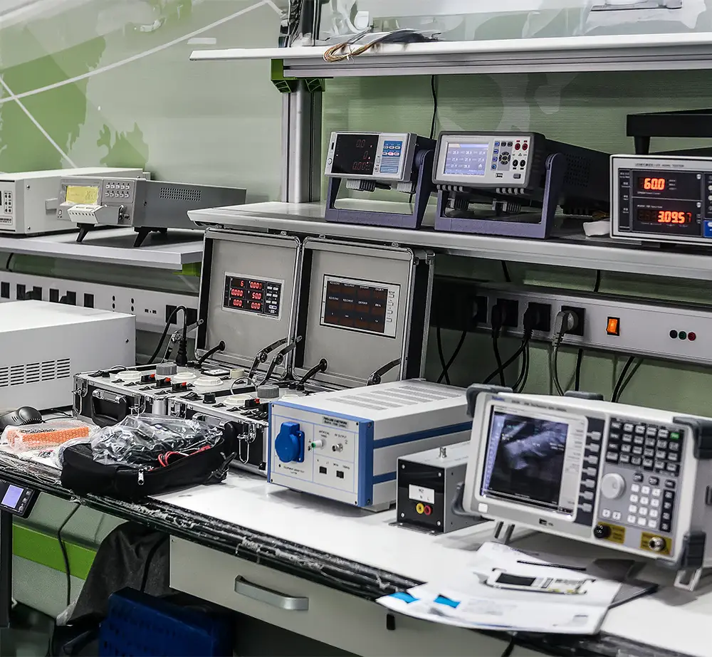
We test with industry-standard instruments, enhanced by our own test framework software.
The architecture UML model is the basis of the software package.
Before we go to the software implementation, we prepare the architecture in the UML model.
For such modeling, we use different tools.
A long time ago, we started with Rational Rhapsody, and now we are using PlantUML, Microsoft Visual Studio, Microsoft Visio, Lucid Chart, and Enterprise Architect.

We adjust the architecture appropriately, whether we build on an operating system – Linux or Windows – or bare-metal firmware.
Project management is the backbone of software development.
For the software development process, we use a tool family made by Atlassian.
We have long experience with JIRA, which is used for bug tracking, where we often utilize Agile process flows based on Kanban or Scrum.

And we exploit the main advantage of JIRA, which is its close connection to the Bitbucket repository.
Version control brings an opportunity for reviews.
For the revision control system, we started with SVN a few years ago. During the last years, we have migrated to toolchains based on Git, which brings the benefit of flexible branching and merging (when compared to SVN). We push data to a remote Bitbucket repository that offers powerful infrastructure and integration with other tools by Atlassian.

We have been using Continuous Integration (CI) technologies like Jenkins Server.
Each team member had experience with different tools for coding.
Our colleagues are not forced to use specific tools. Most of them like using Visual Studio Code (VS Code) or MS Visual Studio; others like Atom, Eclipse, or any simple Linux-based editors.
We utilize static code analysis tools like Clang for the source files.

Almost all the tools offer the full power of a remote-target debugger and various plug-in packages.
We use the best programming language fitting to the individual software package.
Most of programming languages we use have strong support for both Linux and Windows operating systems.
Some of us like Python for its flexibility and no need to compile, especially for fast software prototyping or test scripts.
For the web-based applications, we have good experience with JavaScript, TypeScript, and various web frameworks like ReactJS, and Express supported by runtimes like NodeJS and Electron.

On the other hand, the colleagues who are deeply involved in the lower-level ARM Cortex embedded firmware applications are good in C or C++.
Device Drivers
Some projects require PCIe cards for a host PC. Such computers mostly run on Windows; therefore, we support our customers by the development of Windows drivers.
Of course, we create drivers for embedded Linux as well – in most cases, for the peripherals that are not a part of the individual SOM (system on module).

We have detailed experience with the older Windows Driver Kit (WDK) and newer Kernel-Mode Driver Framework (KMDF).


